TM 10-3930-641-34-1
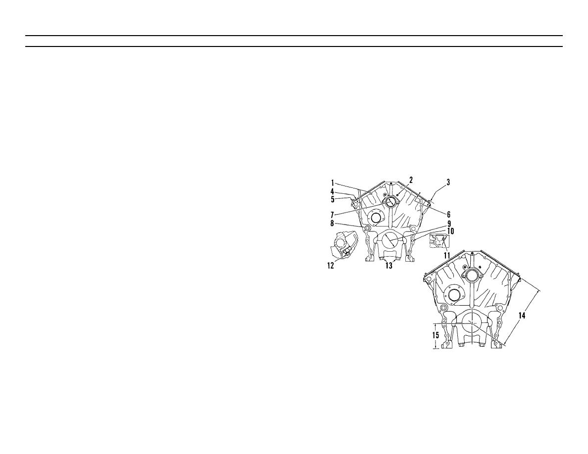
CYLINDER BLOCK SPECIFICATIONS
(Sheet 1 of 1)
(1)
Torque for three studs to hold
c.
Tighten the bolts on right side
the water pump...................................20 + 3 lb. ft. (27 + 4 N.m)
to ..........................................190 + 10 lb. ft. (258 + 14 N.m)
(2)
Plug (two on front and two on rear). See note below.
d. Put a mark on each bolt and cap.
e. Tighten the bolts on right side, from the mark ................. 120
(3)
Length of dowels (four) out of the
f. Tighten the bolts on left side, from the mark ................... 120
block face ....................................... .73 + .02 in. (18.5 + 0.5 mm)
(4)
Thickness of the gasket between the cylinder block and
NOTE
top plates ................................... 008 + .001 in. (0.20 + 0.03 mm)
Put sealer on the threads of 20 plugs installed without a
(5)
Thickness of the top
seal, and on two plugs (11) without threads.
plates ......................................... 338 + .001 in. (8.59 + 0.03 mm)
(14)
Dimension (new from centerline of crankshaft bearing bore to top of
(6)
Refer to CYLINDER LINER PROJECTION, for the height of the liner.
block (top deck) ................ 16.500 + .006 in. (419.10 + 1.15 mm)
(7)
Bore in the block for the camshaft bearings
(15)
Dimension (new) from centerline of crankshaft bearing bore to
(five bores) ................... 3.0250 + .0007 in. (76.835 + 0.018 mm)
bottom of
(8)
Torque for one plug on front and two on rear of the block (see
block (pan rails) ................. 6.500 + .004 in. (165.10 + 0.10 mm)
note below) .....................................60 + 10 lb. ft. (82 + 14 N-m)
(9)
Bore in the block for the main bearings: standard, original size
(new)........................... 5.1138 + .0005 in. (129.891 + 0.013 mm)
.025 in. (0.64 mm) larger than original
size ............................ 5.1388 + .0005 in. (130.526 + 0.013 mm)
(10)
Length of dowels (four) out of the front and rear
faces of the block ............................ 75 + .02 in. (19.1 + 0.5 mm)
(11)
Plug without threads (two) near the front and near the rear of the
cylinder block, on top. See note below.
(12)
Torque for the eight bolts that hold the piston
cooling tubes ......................................18 + 5 lb. ft. (24 + 7 N.m)
(13)
the main bearing caps with the marks (arrow) toward the front of the
engine.
Install each cap in the same place from where it was
removed. The cap with number 1 on its bottom goes in the front of
the block. All other caps also have numbers for position.
a. Put engine oil on the threads of the bolts.
b. Tighten the bolts on left side
to ..........................................190 + 10 lb. ft. (258 + 14 N.m)
TA098816
2-86


