TM 10-3930-641-34-1
CONNECTING ROD SPECIFICATIONS
(Sheet 1 of 1)
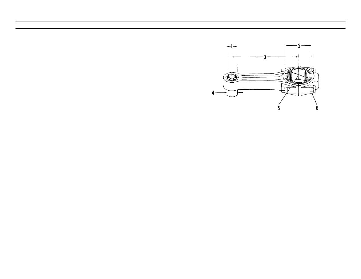
(1)
Bore in bearing for piston
pin (new)................. 2.1820 to 2.1830 in. (55.423 to 55.449 mm)
Maximum permissible clearance between
bearing and piston pin (worn) ......................... 003 in. (0.08 mm)
(2)
Bore in connecting rod for bearing, with nuts tight to specifications
(6) ............................. 4.0748 .0005 in. (103.500 + 0.013 mm)
(3)
Distance between center of
bearings............................ 10.300 + .002 in. (261.62 0.05 mm)
(4)
Diameter of piston pin
(new)............................. 1.9998 + .0002 in. (50.795 + 0.005 mm)
(5)
Bore in bearing for
crankshaft............... 3.8236 to 2.8258 in. (97.119 to 97.175 mm)
Clearance between bearing and crankshaft
(new)................................ 0028 to .0066 in. (0.071 to 0.168 mm)
Maximum permissible clearance between bearing
and crankshaft (worn)..................................... 010 in. (0.25 mm)
(6)
Torque on nut for connecting rod:
a. Put engine oil on threads and nut seat.
NOTE
b. Tighten both nuts to .....................60 + 6 lb. ft. (82 + 8 N.m)
The connecting rod must be installed so the chamfer on
Mark each nut and end of bolt.
d. Again tighten both nuts (from mark) ................................ 120
the edge of bore (5) is near the comer on the crankshaft.
The flat side of bore (5) must be against the other
connecting rod on the same crankshaft pin.
Side clearance between two connecting rods on same
crankshaft pin
(new)........................................ 011 to .029 in. (0.28 to 0.74 mm)
TA098820
2-90


