TM 10-3930-675-20-1
0010 00-4
OVERLOAD PROTECTION TROUBLESHOOTING - CONTINUED
0010 00
Table 3. Error Code 132 - Boom Angle Sensor or Circuit Failure Troubleshooting Procedures - Continued.
MALFUNCTION
TEST OR INSPECTION
CORRECTIVE ACTION
Error Code 132 - Boom Angle Sensor or Circuit
Failure - Continued
5. Perform
voltage
check
between connector X157 pin
2 and pin 3. Voltage should be
10V.
a. If voltage is present, check
continuity
between
connector X157 pin 2 and
junction box X169 pin 2,
between connector X157
pin 3 and junction box
X169 pin 3, and between
connector X157 pin 4 and
junction box X169 pin 4.
If continuity is not present,
repair or replace connectors (WP
0111 00).
b. If voltage was present, enter
the “DIAG SERVO 1 (13)”
menu and check voltage of
10V REF OUT. Voltage
should be 10V.
a. If voltage is not as specified,
replace ECU (790) (WP 0079
00).
b. If voltage is as specified,
notify SRA.
Table 4. Error Code 133 - Left Lift Cylinder Pressure Sensor or Circuit Failure Troubleshooting Procedures.
MALFUNCTION
TEST OR INSPECTION
CORRECTIVE ACTION
Error Code 133 - Left Lift Cylinder Pressure
Sensor or Circuit Failure
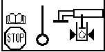
1. Inspect left lift cylinder
sensors and connectors for
damage and secure mounting.
Two sensors are located at
locking valve at base of lift
cylinder.
DIAG SERVO
1(13)
SYSTEM POWER
24.00V
POWER RI CAN
24.00V
POWER LE CAN
24.00V
10V REF OUT
10.00V