TM 10-3930-675-20-1
0010 00-6
OVERLOAD PROTECTION TROUBLESHOOTING - CONTINUED
0010 00
Table 5. Error Code 134 - Right Lift Cylinder Pressure Sensor or Circuit Failure
Troubleshooting Procedures.
MALFUNCTION
TEST OR INSPECTION
CORRECTIVE ACTION
Error Code 134 - Right Lift Cylinder Pressure
Sensor or Circuit Failure
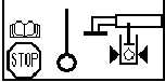
1. Inspect right lift cylinder
sensors and connectors for
damage and secure mounting.
Two sensors are located at
locking valve at base of lift
cylinder.
2. Remove cover from junction
box X167, located at forward
end of engine compartment.
Start
engine
and
check
voltage between pin 16 and
pin 17. Voltage should be 20-
25V.
If voltage is present, check
voltage at junction box X167
pin 18. Voltage should be 0.3-
10.8V depending on actual
hydraulic pressure.
If voltage is not present, replace
right cylinder pressure sensor
(WP 0101 00).
3. Remove ECU (790) cover
from operator’s seat base and
slide ECU mounting tray out
(WP 0079 00).
4. Check ECU (790) connector
1, connector X159, and ECU
tray grounding leads for
proper connection.
a. Connect
any
loose
or
disconnected
connections.
Push ECU mounting tray in
and install cover.
b. Repair
or
replace
any
damaged connectors (WP
0111
00).
Push
ECU
mounting tray in and install
cover.
5. Perform voltage check at
connector
X159
pin
3.
Voltage should be 20-25V.
DIAG SERVO
1(13)
SYSTEM POWER
24.00V
POWER RI CAN
24.00V
POWER LE CAN
24.00V
10V REF OUT
10.00V