TM 10-3930-675-20-2
0076 00-1
TOPHANDLER JUNCTION BOX MAINTENANCE
0076 00
THIS WORK PACKAGE COVERS
Tophandler Electronic Control Unit (ECU): Removal,
Installation
Relay: Removal, Installation
INITIAL SETUP
Tools and Special Tools
Tool kit, general mechanic’s (Item 31, WP 0204 00)
Materials/Parts
Tag, marker (Item 28, WP 0203 00)
References
WP 0197 00
WP 0199 00
Equipment Condition
Master battery switch in OFF position
TOPHANDLER ELECTRONIC CONTROL UNIT (ECU) REMOVAL
NOTE
Tophandler ECU is located inside junction box at end of boom, above tophandler. Tophandler ECU is identi-
fied as no. 791 on system electrical diagrams (WP 0199 00).
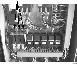
1.
Loosen six screws (1) and remove cover (2) of tophandler junction box (4). Note that three circuit breakers (5) should be
in ON position.
2.
Inspect rubber seal (3) of cover (2). Replace only if damaged.
1
2
3
4
5