TM 10-3930-675-24-2
FLYWHEEL HOUSING REPLACEMENT - CONTINUED
0205 00
ALIGNMENT - CONTINUED
CAUTION
DO NOT allow tip of gage to enter capscrew holes while performing face alignment check. If tip of
gage enters holes, gage will be damaged.
2.
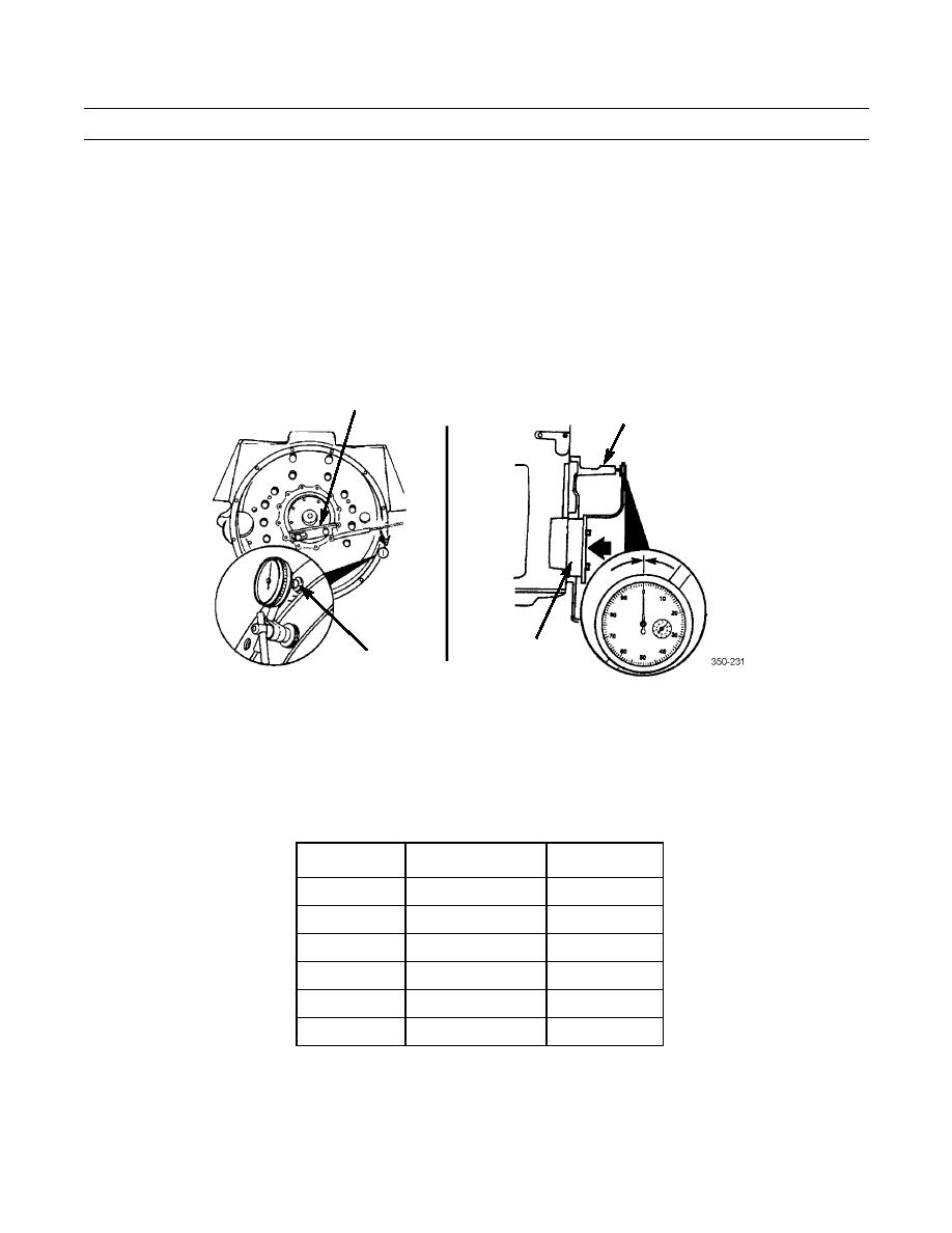
Perform flywheel housing face alignment as follows:
a.
Position contact tip of dial indicator gage (8) against flywheel housing (4) face.
b.
Push crankshaft (11) toward front of engine.
c.
Adjust gage dial to "0" (zero).
10
4
11
8
d.
Using engine barring tool (10), rotate crankshaft one complete revolution and record reading.
e.
Compare recorded reading to Table 3 for SAE number of flywheel housing being installed. If maximum face align-
ment does not meet specification, and no visible damage or defects have been detected, flywheel housing must be
replaced.
Table 3. Flywheel Housing Face Alignment Maximum TIR.
MM
SAE NO.
IN.
0.31
00
0.012
0.25
0
0.010
0.25
0.010
0.20
1
0.008
0.20
2
0.008
0.20
3
0.008
3.
Using gage block (12), check alignment of oil pan flange of flywheel housing (13) with cylinder block oil pan mounting
flange (7). Flywheel housing oil pan flange must be even with cylinder block oil pan mounting flange to within 0.006
in. (0.15 mm).
0205 00-8


