TM 10-3930-675-24-2
ROCKER ARM ASSEMBLY MAINTENANCE - CONTINUED
0206 00
INSTALLATION - CONTINUED
f.
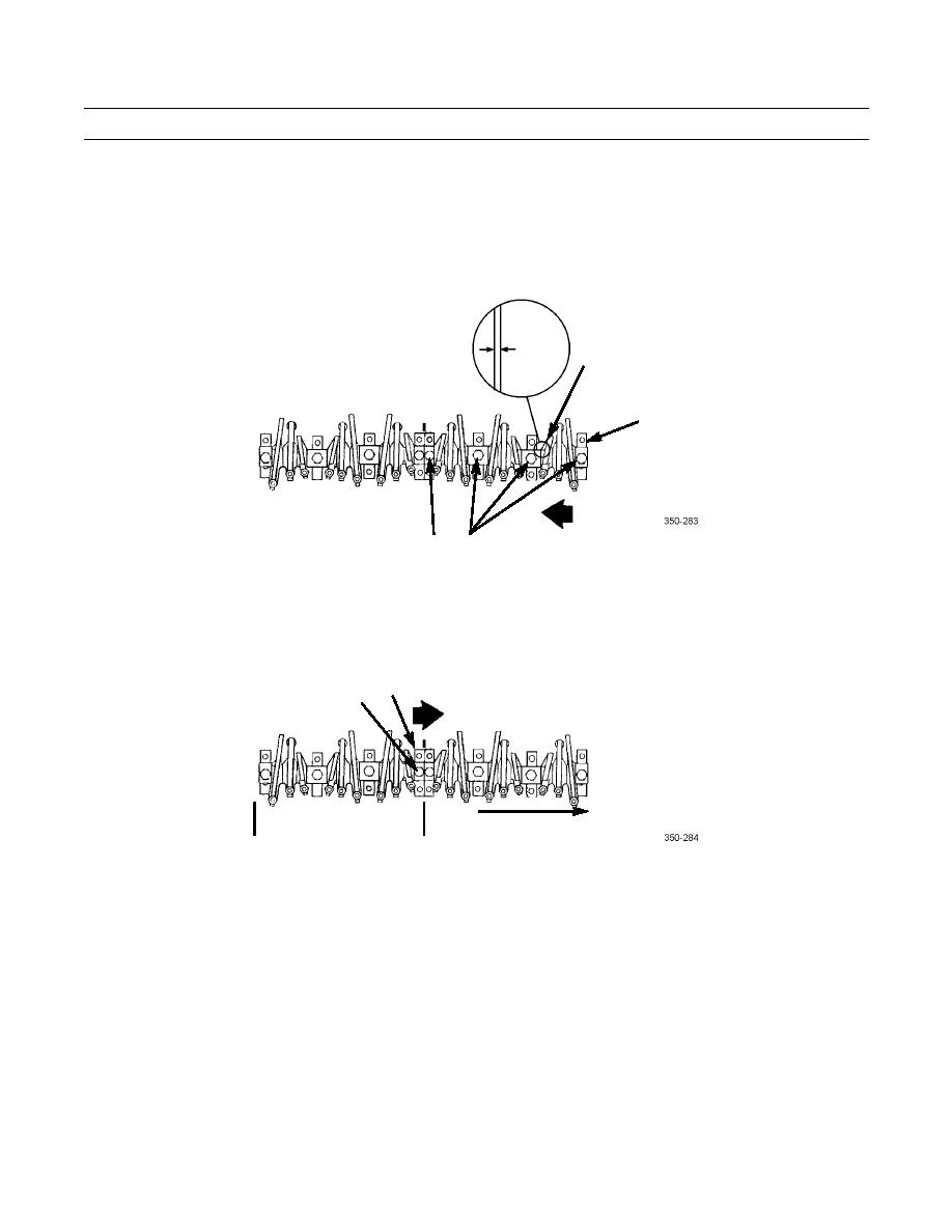
Insert 0.020 in. (0.50 mm) feeler gage between number seven support (6) and intake lever for number six cylinder.
g.
Push or tap number eight support (13) toward front of engine.
h.
Fully tighten four support mounting screws (8) to 135 lb-ft (183 Nm).
0.50 MM
INTAKE
LEVER
(0.020 IN.)
13
8
8
3.
Set side clearance for front section of rocker arm assembly as follows:
a.
Push or use hammer to tap number four support (13) toward rear of engine. Tighten mounting screw (8) to 45 lb-in.
(5 Nm).
13
8
FRONT SECTION
REAR OF ENGINE
0206 00-9


