
TM 9-3950-253-13&P
0007
WARNING
Check for overhead wires or cables and verify adequate clearance to complete operation.
Failure to follow this warning may result in damage to equipment and injury or death to
personnel. Seek medical attention in the event of an injury.
RETRIEVE LIFT FRAME
Retrieve Lift Frame - Stage 1
NOTE
If lift frame is to be placed on ground, slider beds can be in either configuration.
1.
Verify these conditions exist:
a.
Lift mechanism in home position (PLS: TM 9-2320-364-14&P, HEMTT: TM 9-2320-326-14&P).
b.
Vehicle in neutral gear and parking brake applied (PLS: TM 9-2320-364-14&P,
HEMTT: TM 9-2320-326-14&P).
c.
MODE switch set to OFF (PLS: TM 9-2320-364-14&P, HEMTT: TM 9-2320-326-14&P).
2.
Start engine and run at idle speed (PLS: TM 9-2320-364-14&P, HEMTT: TM 9-2320-326-14&P).
3.
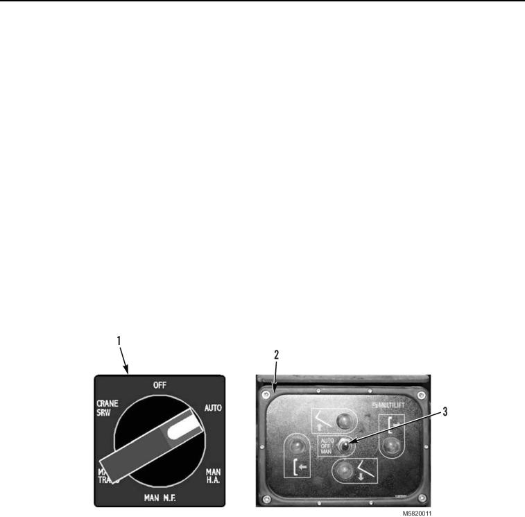
In cab, set MODE switch (Figure 1, Item 1) to AUTO position (PLS: TM 9-2320-364-14&P,
HEMTT: TM 9-2320-326-14&P).
4.
At stowage control panel (Figure 1, Item 2) set toggle switch (Figure 1, Item 3) to AUTO position.
Figure 1. MODE Switch and Stowage Control Panel.
5.
Press and hold UP button (Figure 2, Item 1) until hook arm frame rises by approximately 4 in. (10 cm) and
stops. Release UP button.
03/15/2011Rel(1.10)root(opusualwp)wpno(O582007)