TM 9-3950-253-13&P
0071
DISASSEMBLY - Continued
6.
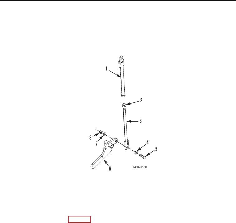
Remove locknut (Figure 3, Item 8), washer (Figure 3, Item 7), washer (Figure 3, Item 4), bolt (Figure 3,
Item 5), and latch handle (Figure 3, Item 6) from adjustment bar (Figure 3, Item 3). Discard locknut.
7.
Loosen nut (Figure 3, Item 2) and remove adjustment bar (Figure 3, Item 3) from latch rod (Figure 3,
Item 1).
Figure 3. Latch Handle.
END OF TASK
CLEANING AND INSPECTION
Clean and inspect all parts IAW (WP 0061), General Maintenance Instructions.
END OF TASK
ASSEMBLY
NOTE
Install latch rod as noted during removal.
1.
Install latch rod (Figure 3, Item 1) and nut (Figure 3, Item 2) on adjustment bar (Figure 3, Item 3) keeping
rod ends parallel.
2.
Install latch handle (Figure 3, Item 6), bolt (Figure 3, Item 5), washer (Figure 3, Item 4), washer (Figure 3,
Item 7), and new locknut (Figure 3, Item 8) on adjustment bar (Figure 3, Item 3).
03/15/2011Rel(1.10)root(maintwp)wpno(M582070)

