TM 9-3950-253-13&P
0085
INSTALLATION
NOTE
Route and install pneumatic lines as noted and tagged during removal.
Latch Actuator Hose Installation
1.
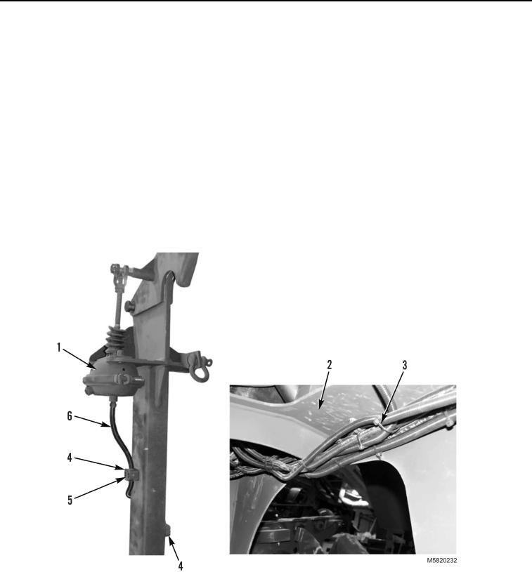
Route latch actuator hose (Figure 7, Item 6) from under stowage assembly (Figure 7, Item 2) toward latch
actuator (Figure 7, Item 1).
2.
Install new tiedown straps (Figure 7, Item 3) as required.
3.
Install latch actuator hose (Figure 7, Item 6) in three hose clamps (Figure 7, Item 4) and tighten six screws
(Figure 7, Item 5).
4.
Install latch actuator hose (Figure 7, Item 6) on latch actuator (Figure 7, Item 1).
Figure 7. Latch Actuator Hose Removal.
5.
Install latch actuator hose (Figure 8, Item 4) on solenoid valve (Figure 8, Item 3).
6.
Install solenoid cover (Figure 8, Item 2) on stowage assembly (Figure 8, Item 5) and tighten three locking
screws (Figure 8, Item 1).
03/15/2011Rel(1.10)root(maintwp)wpno(M582084)

