
TM 9-3950-253-13&P
0091
CONVERT TO STANDARD CONFIGURATION
1.
Perform these procedures with vehicle stationary, parking brake applied, neutral gear selected, engine on,
MODE switch set to AUTO, and PTO switch ON (HEMTT only) (PLS: TM 9-2320-364-14&P, HEMTT: TM
9-2320-326-14&P).
2.
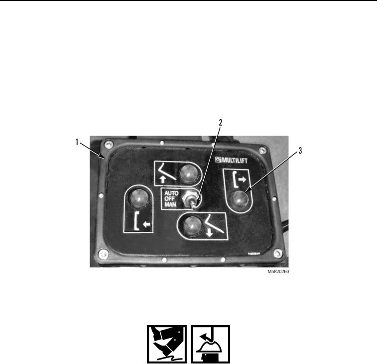
With lift frame in transport position, set stowage toggle switch (Figure 9, Item 2) to MAN position.
3.
Press and hold RETRIEVE button (Figure 9, Item 3) on stowage control panel (Figure 9, Item 1) to move
stowage guide rearward. When stowage guide stops, release RETRIEVE button.
4.
Set stowage toggle switch (Figure 9, Item 2) to OFF position and turn off engine.
Figure 9. Stowage Control Panel.
WARNING
During these procedures, the operator will be required to climb on and around the vehicle.
Be sure to wear suitable footwear, ensure no surfaces are slippery, wear suitable gloves
and hard hat and maintain three points of contact to the vehicle. Failure to follow this
warning may result in injury to personnel. Seek medical attention in the event of an injury.
5.
Remove clip pin (Figure 10, Item 1) from locking pin (Figure 10, Item 3).
6.
Remove locking pin (Figure 10, Item 3) from upper position on latch support bracket (Figure 10, Item 4).
7.
Raise latch support beam (Figure 10, Item 2) to vertical position and install locking pin (Figure 10, Item 3) in
latch support bracket (Figure 10, Item 4).
8.
Install clip pin (Figure 10, Item 1) in locking pin (Figure 10, Item 3).
03/15/2011Rel(1.10)root(maintwp)wpno(M582090)