TM 10-3930-675-24-2
BOOM WIRING HARNESSES REPLACEMENT
THIS WORK PACKAGE COVERS
Removal, Installation
INITIAL SETUP
References
Maintenance Level
TM 10-3930-675-10
Direct Support
Tools and Special Tools
Equipment Condition
Tool Kit, General Mechanic's (Item 128, WP 0289
Master battery switch in OFF position
Materials/Parts
Strap, Tiedown (Item 37, WP 0290 00)
NOTE
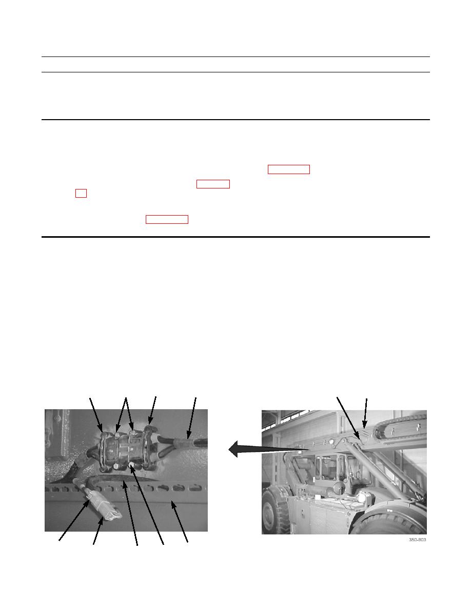
Two wiring harnesses are routed along right side of boom and boom extension and terminate at
tophandler junction box. This work package describes replacement of these two wiring harnesses.
REMOVAL
1.
Disconnect wiring harness (5) connector (9) from chassis wiring harness connector (10).
2.
Remove four screws (2). Disconnect wiring harness (4) connector (3) from chassis wiring harness connector (1).
NOTE
Note routing of wiring harnesses and positioning of tiedown straps to assist in installation.
3.
Trace wiring harnesses (4 and 5) along boom (6), removing and discarding all tiedown straps that secure wiring har-
nesses to channels (8).
4,5
3
1
2
4
6
10
8
9
2
5


