
TM 9-3950-253-13&P
0008
ATTACH LIFT FRAME TO CONTAINER - Continued
Checks
1.
Verify both upper guides are fully lowered into apertures on top of container.
2.
Verify both lower locking pins are inserted in corner castings of container.
3.
Verify anti-loose fastener on each lower guide is locked.
4.
Verify bail bar lock is installed on hook.
END OF TASK
LOAD CONTAINER
WARNING
Bail bar lock MUST be securely installed before continuing with procedure. Without bail bar
lock installed, lift frame and container may disengage from hook and fall to the ground.
Failure to follow this warning may result in injury or death to personnel. Seek medical
attention in the event of an injury.
1.
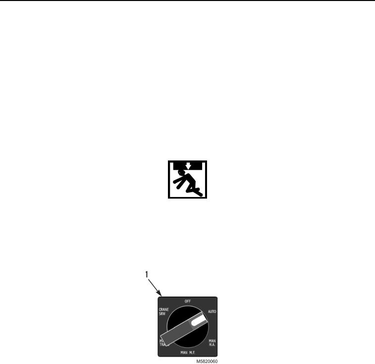
With engine at idling speed, set MODE switch (Figure 7, Item 1) to AUTO (PLS: TM 9-2320-364-14&P,
HEMTT: TM 9-2320-326-14&P).
Figure 7. MODE Switch at AUTO.
2.
Keeping engine at idling speed, set joystick (Figure 8, Item 1) to LOAD (PLS: TM 9-2320-364-14&P,
HEMTT: TM 9-2320-326-14&P) to raise front of container (Figure 8, Item 2) approximately 8 in. (20 cm) from
ground. At this point, release parking brake.
03/15/2011Rel(1.10)root(opusualwp)wpno(O582008)