
TM 9-3950-253-13&P
0070
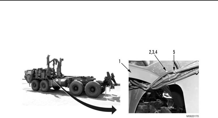
STOWAGE GUIDE SENSOR HARNESS REMOVAL - Continued
4.
Underneath stowage assembly (Figure 10, Item 1), remove and discard tiedown straps (Figure 10, Item 5)
as required.
5.
Remove 13 nuts (Figure 10, Item 2), bolts (Figure 10, Item 3), and clamps (Figure 10, Item 4) from stowage
assembly (Figure 10, Item 1).
Figure 10. Clamp and Tiedown Strap Removal.
END OF TASK
CONTROL BOX REMOVAL
1.
Loosen four bolts (Figure 11, Item 15) and remove cover (Figure 11, Item 16) from Space 4000 ST box
(Figure 11, Item 14).
2.
Loosen four bolts (Figure 11, Item 2) and remove cover (Figure 11, Item 3) from Relay box (Figure 11,
Item 17).
3.
Loosen four bolts (Figure 11, Item 5) and remove cover (Figure 11, Item 4) from Additional MUX box
(Figure 11, Item 6).
4.
Remove four bolts (Figure 11, Item 11), washers (Figure 11, Item 12), spacers (Figure 11, Item 13), and
Space 4000 ST box (Figure 11, Item 14) from support bracket (Figure 11, Item 1) and place on flat work
surface.
5.
Remove four bolts (Figure 11, Item 7), washers (Figure 11, Item 8), and Additional MUX box (Figure 11,
Item 6) from support bracket (Figure 11, Item 1) and place on flat work surface.
6.
Remove four bolts (Figure 11, Item 9), washers (Figure 11, Item 10), and Relay box (Figure 11, Item 17)
from support bracket (Figure 11, Item 1) and place on flat work surface.
03/15/2011Rel(1.10)root(maintwp)wpno(M582069)