
TM 9-3950-253-13&P
0070
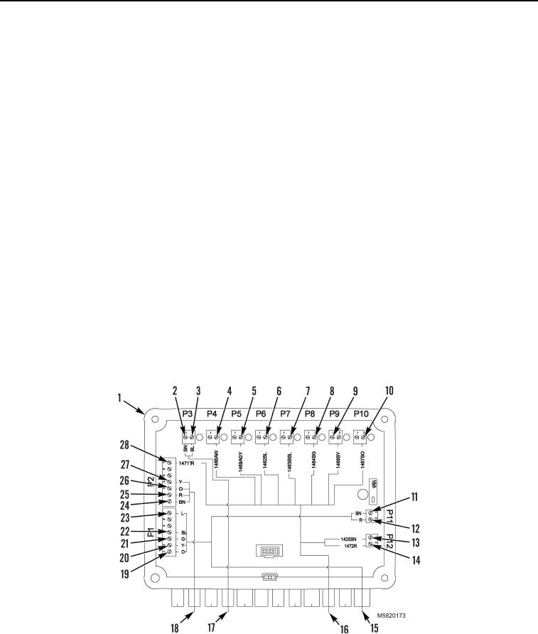
RELAY BOX WIRING REMOVAL
1.
Disconnect orange wire from position 1 (Figure 13, Item 19), yellow wire from position 2 (Figure 13,
Item 20), green wire from position 3 (Figure 13, Item 21), blue wire from position 4 (Figure 13, Item 22), and
lilac wire from position 7 (Figure 13, Item 23) on P1.
2.
Disconnect brown wire from position 1 (Figure 13, Item 11), and red wire from position 2 (Figure 13,
Item 12) on P11.
3.
Remove CAN bus harness (Figure 13, Item 15) from Relay box (Figure 13, Item 1).
4.
Disconnect brown wire from position 1 (Figure 13, Item 24), red wire from position 2 (Figure 13, Item 25),
orange wire from position 3 (Figure 13, Item 26), and yellow wire from position 4 (Figure 13, Item 27), on P2.
5.
Remove CAN bus harness (Figure 13, Item 18) from Relay box (Figure 13, Item 1).
6.
Disconnect brown wire from position 1 (Figure 13, Item 2), and blue wire from position 2 (Figure 13, Item 3),
on P3.
7.
Remove stowage latch harness (Figure 13, Item 17) from Relay box (Figure 13, Item 1).
8.
Disconnect 1471 wire from position 7 (Figure 13, Item 28) on P2,1466 wire from position 2 (Figure 13,
Item 4) on P4, 1469 wire from position 2 (Figure 13, Item 5) on P5, and 1462 wire from position 2
(Figure 13, Item 6) on P6.
9.
Disconnect 1463 wire from position 2 (Figure 13, Item 7) on P7, 1464 wire from position 2 (Figure 13,
Item 8) on P8, 1468 wire from position 2 (Figure 13, Item 9) on P9, and 1467 wire from position 2
(Figure 13, Item 10) on P10.
10.
Disconnect 1435 wire from position 1 (Figure 13, Item 13) on P12, and 1472 wire from position 2 (Figure 13,
Item 14) on P12.
11.
Remove stowage loom harness (Figure 13, Item 16) from Relay box (Figure 13, Item 1).
Figure 13. Relay Box Wiring Removal.
END OF TASK
03/15/2011Rel(1.10)root(maintwp)wpno(M582069)