TM 9-3950-253-13&P
0075
MIDDLE FRAME SENSOR INSTALLATION AND CALIBRATION
1.
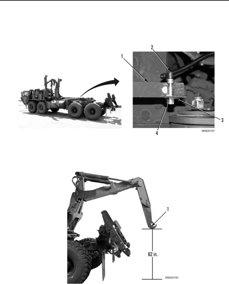
Connect electrical connector (Figure 11, Item 2) to middle frame sensor (Figure 11, Item 4).
2.
Insert middle frame sensor (Figure 11, Item 4) into bracket (Figure 11, Item 1) and loosely install locking nut
(Figure 11, Item 3).
Figure 11. Middle Frame Sensor.
3.
With MODE switch set to AUTO position, extend hook arm (PLS: TM 9-2320-364-14&P,
HEMTT: TM 9-2320-326-14&P) until bottom of hook (Figure 12, Item 1) is 62 in. (1,574.8 mm) from ground.
Figure 12. Hook Position from Ground.
03/15/2011Rel(1.10)root(maintwp)wpno(M582074)

