
TM 9-3950-253-13&P
0075
LIFT FRAME SENSOR INSTALLATION AND CALIBRATION
CAUTION
Incorrectly installed and configured sensors may result in damage to equipment.
1.
Loosen two bolts (Figure 6, Item 1) in cable clamp (Figure 6, Item 2) and insert lift frame sensor (Figure 6,
Item 4) into clamp.
2.
Adjust lift frame sensor (Figure 6, Item 4) placement until end of sensor is flush with cable clamp (Figure 6,
Item 2) and tighten two bolts (Figure 6, Item 1).
3.
Connect electrical connector (Figure 6, Item 3) to lift frame sensor (Figure 6, Item 4).
4.
Load and stow lift frame (WP 0007).
5.
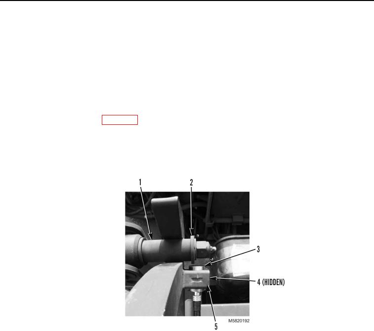
Loosen two bolts (Figure 7, Item 4) in cable clamp (Figure 7, Item 5).
6.
Adjust lift frame sensor (Figure 7, Item 3) placement until face of sensor is 0.0625 to 0.1875 in. (2 to 3 mm)
from collar (Figure 7, Item 2) on roller pin (Figure 7, Item 1) and tighten two bolts (Figure 7, Item 4).
Figure 7. Lift Frame Sensor Calibration.
END OF TASK
03/15/2011Rel(1.10)root(maintwp)wpno(M582074)