TM 9-3950-253-13&P
0075
HOOK ARM SENSOR INSTALLATION AND CALIBRATION
1.
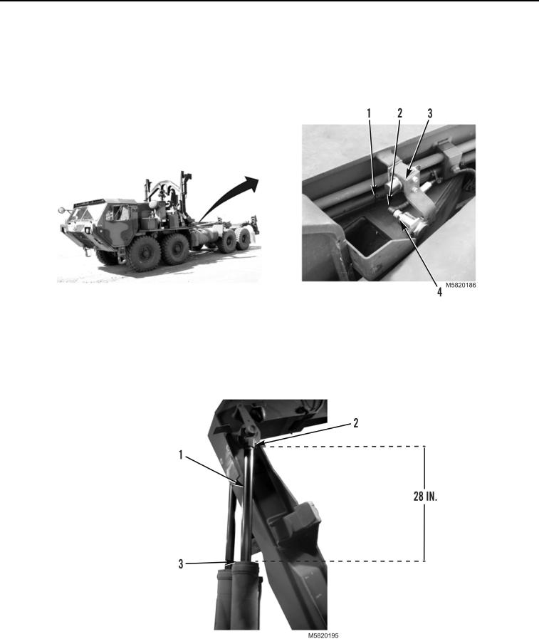
Insert hook arm sensor (Figure 14, Item 2) into bracket (Figure 14, Item 3) and loosely install locking nut
(Figure 14, Item 4).
2.
Connect electrical connector (Figure 14, Item 1) to hook arm sensor (Figure 14, Item 2).
Figure 14. Hook Arm Sensor Installation.
3.
With MODE switch set to AUTO position, partially extend hook arm (PLS: TM 9-2320-364-14&P,
HEMTT: TM 9-2320-326-14&P) until cylinder arm (Figure 15, Item 1) is extended 28 in. (711 mm) measured
from base of cylinder arm cap (Figure 15, Item 2) to top of cylinder casing (Figure 15, Item 3).
Figure 15. Hook Arm Cylinder Extension.
4.
Shut off vehicle and set ignition switch to ON position (PLS: TM 9-2320-364-14&P,
HEMTT: TM 9-2320-326-14&P).
03/15/2011Rel(1.10)root(maintwp)wpno(M582074)

