TM 10-3930-675-20-2
0102 00-3
HYDRAULIC FILTER INDICATOR SENSORS REPLACEMENT - CONTINUED
0102 00
REMOVAL - CONTINUED
5.
Remove sensor (4) with cable (3) from filter head (5).
INSTALLATION
NOTE
•
Use electrically conductive grease on wire connections before connections are made.
•
Install new tiedown straps as necessary.
1.
Install sensor (4) to filter head (5).
2.
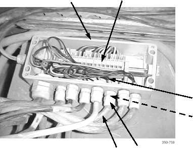
Feed cable (3) thru grommet (9) and cable nut (10) and into junction box (6).
3.
Using a jeweler’s screwdriver, connect cable wires (8) to terminal blocks (7).
4.
Install grommet (9) and cable nut (10) to junction box (6). Tighten cable nut.
5.
Install cover (1) on junction box (6) and tighten four screws (2).
6.
Install transmission access cover(s) (WP 0135 00).
7.
Return cab to operational position (TM 10-3930-675-10).
END OF WORK PACKAGE
6
7
8
9
10
3