TM 10-3930-675-24-2
CAM FOLLOWER ASSEMBLY MAINTENANCE - CONTINUED
0275 00
INSPECTION - CONTINUED
4.
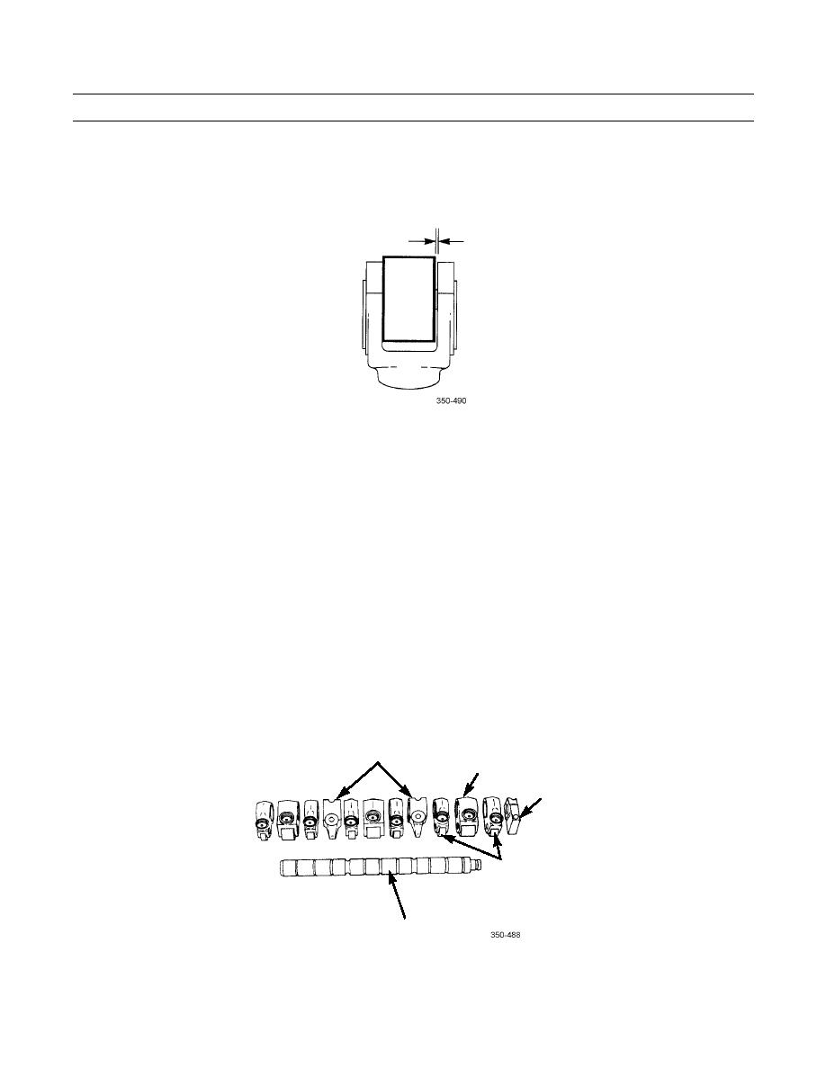
Measure roller side clearance of cam follower lever. Measurement must be 0.007 to 0.026 in. (0.19 to 0.65 mm). If not
as specified, replace cam follower lever.
ROLLER SIDE CLEARANCE
ASSEMBLY
1.
Using clean engine oil, lubricate cam follower shaft and cam follower levers.
NOTE
Cam follower levers have established wear patterns and MUST be installed in the same position from
which they were removed.
2.
Install end support on shaft.
3.
Install intake valve cam follower lever, injector cam follower lever, exhaust valve cam follower lever, and shaft support
on shaft in same position as noted during disassembly.
4.
Install remaining valve cam follower levers, injector cam follower levers, and supports as noted during disassembly.
INJECTOR CAM
SHAFT SUPPORT
FOLLOWER LEVER
END
SUPPORT
VALVE CAM
FOLLOWER LEVER
CAM FOLLOWER
SHAFT
0275 00-5


