
TM 10-3930-675-24-2
CAM FOLLOWER ASSEMBLY MAINTENANCE - CONTINUED
0275 00
INSTALLATION - CONTINUED
9.
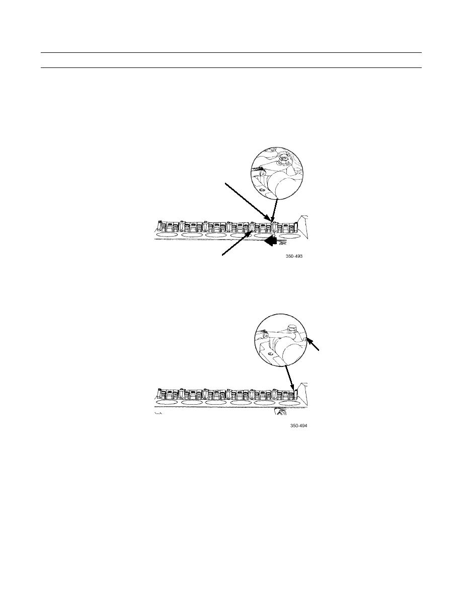
Install 0.030 in. (0.76 mm) thickness gage between no. 2 cam follower shaft support and intake lever for cylinder no. 2.
10.
Push no. 2 cam follower levers toward no. 3 cam follower shaft support.
11.
Tighten no. 2 cam follower stud nut to 35 lb-ft (47 Nm).
NO. 2
SUPPORT
NO. 3
SUPPORT
12.
Measure side clearance between no. 1 cam follower levers and end support. Measurement should be 0.030 in. (0.76
mm).
SIDE
CLEARANCE
CHECK
0275 00-8
