TM 5-3810-306-34
INSTALLATION:
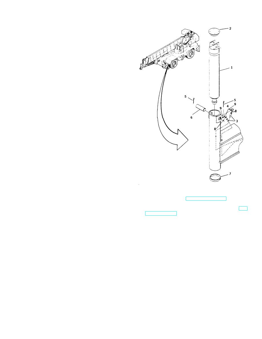
1. INSTALL JACK CYLINDER (1).
a. Install new wear ring (7) in groove in bottom of
cylinder tube.
b. Place a hydraulic jack under cylinder tube.
c.
Using a lifting device, lower jack cylinder into
tube aligning ports with cut-out in tube.
d. Raise hydraulic jack to take up weight of cylinder
and remove lifting device.
e. Lower cylinder (1) into tube until pin (6) can be
installed. Use care not to damage wear ring (7)
or dislodge it.
f.
Coat pin with Never-Seeze and install pin (6) and
two new cotter pins (5) securing cylinder (1) to
tube.
g. Remove the hydraulic jack.
NOTE
Coat new performed packing with
clean hydraulic oil and fittings
threads with Loctite #545.
h. Install hydraulic fittings (4) and new packings (9)
in ports of cylinder.
2. CONNECT NEGATIVE BATTERY CABLE
AT
CAUTION
SHUNT. (REFER TO TM 5-3810-306-20.)
Ensure piston side (extend) of
3. ACTIVATE HYDRAULIC SYSTEM. (REFER TO TM
cylinder is connected to solenoid
5-3810-306-10.)
valve. Reversal of port connection of
rod (retract) and piston (extend)
4. EXTEND AND RETRACT JACK CYLINDER AS
could result in damage to cylinder as
DESCRIBED
UNDER
OUTRIGGER
BEAM
very high pressure will occur.
INSTALLATION.
5. CHECK
FOR
SMOOTH
OPERATION
OF
i.
Connect hydraulic lines (3) And new packings (8)
CYLINDER.
to fittings as tagged during removal.
6. CHECK ALL HYDRAULIC CONNECTIONS AND
j.
Install jack cylinder access cap (2) with
HOSES FOR EVIDENCE OF LEAKAGE.
weatherstrip cement applied in three beads
approximately 120 apart.
END OF TASK
11-16


