TM 9-3950-253-13&P
0064
FOLLOW-ON MAINTENANCE - Continued
3.
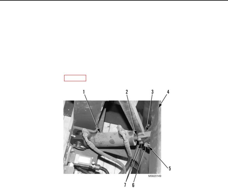
Remove snap ring pin (Figure 2, Item 6), retaining pin (Figure 2, Item 5), and stowage cylinder (Figure 2,
Item 1) from capture frame (Figure 2, Item 4).
4.
Loosen two bolts (Figure 2, Item 7) on cylinder rod end (Figure 2, Item 3).
5.
Hold cylinder shaft (Figure 2, Item 2) in place, and loosen cylinder rod end (Figure 2, Item 3) to desired
position.
6.
Tighten two bolts (Figure 2, Item 7) on cylinder rod end (Figure 2, Item 3).
7.
Install stowage cylinder (Figure 2, Item 1), retaining pin (Figure 2, Item 5), and snap ring pin (Figure 2,
Item 6) on capture frame (Figure 2, Item 4).
8.
Stow lift frame on vehicle (WP 0007). Repeat adjustment procedure as required.
Figure 2. Stowage Cylinder Rod End Adjustment.
END OF TASK
END OF WORK PACKAGE
03/15/2011Rel(1.10)root(maintwp)wpno(M582063)

