TM 10-3930-675-24-2
OIL PUMP ASSEMBLY MAINTENANCE - CONTINUED
0277 00
INSTALLATION - CONTINUED
CAUTION
Grooved side of rear thrust bearing must face toward gear to prevent damage to gear and engine.
6.
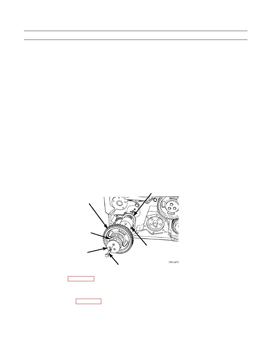
Apply lubriplate to rear thrust bearing (2) and idler gear shaft (3).
7.
Install rear thrust bearing (2) without idler gear shaft (3).
8.
Align inside diameter of rear thrust bearing (2) and inside diameter of idler gear (1).
NOTE
Shaft MUST pass through gear and pilot into rear thrust bearing. After installation, shaft MUST pro-
trude from idler gear only slightly more than thickness of front thrust bearing.
9.
Install idler gear shaft (3) into idler gear (1) bore.
CAUTION
Grooved side of front thrust bearing must face gear to prevent damage to gear and engine.
10.
Apply lubriplate to front thrust bearing (6) and install bearing.
11.
Install cover plate (5) and secure with three screws (4). Tighten screws to 45 lb-ft (61 Nm). Rotate 60 degrees and check
2
1
6
3
5
4
12.
Install water pump (WP 0068 00).
13.
Using dial indicator, verify idler gear end clearance is 0.012 to 0.021 in. (0.30 to 0.53 mm) and backlash is 0.003 to
0.015 in. (0.08 to 0.38 mm).
14.
Install front gear cover (WP 0212 00).
END OF WORK PACKAGE
0277 00-10


