
TM 9-3950-253-13&P
0087
CALIBRATION - Continued
NOTE
Value should be approximately 4.4V when stowage guide is vertical and approximately
0.8V when guide is tilted fully toward rear.
8.
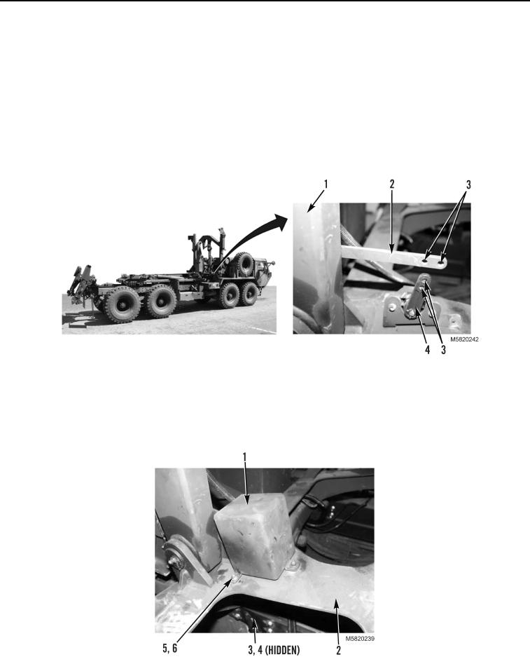
Move stowage guide (Figure 5, Item 1) and watch values on multimeter. Values should range between 0.8V
and 4.4V (approximately) as stowage guide is moved.
9.
If values are out of range, adjust placement of sensor arm (Figure 5, Item 2) on sensor linkage (Figure 5,
Item 4) by installing mounting hardware in different mounting locations (Figure 5, Item 3). Measure current
at new location to ensure value is between 0.8V and 4.4V.
Figure 5. Sensor Arm Placement on Sensor Linkage.
10.
When calibration is complete, install sensor cover (Figure 6, Item 1), three bolts (Figure 6, Item 5), washers
(Figure 6, Item 6), washers (Figure 6, Item 3), and new locknuts (Figure 6, Item 4) on stowage assembly
(Figure 6, Item 2).
Figure 6. Sensor Cover Installation.
03/15/2011Rel(1.10)root(maintwp)wpno(M582086)