
TM 9-3950-253-13&P
0086
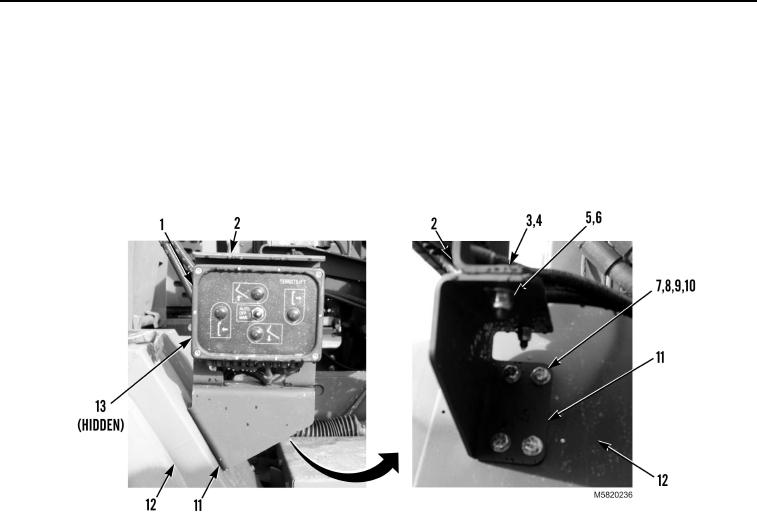
INSTALLATION - Continued
3.
Install bracket (Figure 6, Item 11), four washers (Figure 6, Item 10), bolts (Figure 6, Item 9), washers
(Figure 6, Item 8), and new locknuts (Figure 6, Item 7) on fender (Figure 6, Item 12).
4.
Install backplate (Figure 6, Item 2), two washers (Figure 6, Item 4), bolts (Figure 6, Item 3), washers
(Figure 6, Item 5), and new locknuts (Figure 6, Item 6) on bracket (Figure 6, Item 11).
5.
Install stowage control unit (Figure 6, Item 1) and four bolts (Figure 6, Item 13) on backplate (Figure 6,
Item 2).
Figure 6. PLS M1075A1 Stowage Control Unit Installation.
03/15/2011Rel(1.10)root(maintwp)wpno(M582085)